views
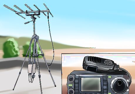
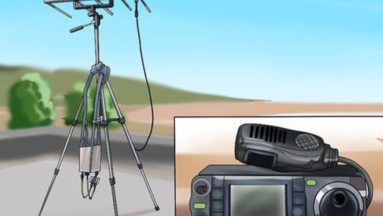
Emphasis on the Antenna! The heart of the system of Amateur Radio is the antenna. There are many other misinformed persons stating that power is the ultimate force. Not So ! The heart of any radio station, be it Amateur Radio, Commercial, Business, CB, Personal Family Radio, or experimenters in extremely low power amateur radio ( QRP as it is called ) transmissions IS the antenna! Without good reception, you won't hear much. Without good antennas for transmitting, you won't transmit far, even if you apply high output RF power, or if high output watts are used !
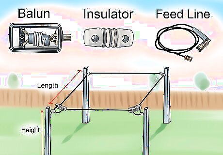
Planning an antenna project can lead to many different thoughts and you should always consider the following. Height, length, feedline, balun, (and we will talk about a balun later), insulators, type wire used, or type metal used, what do you want to do with this antenna, how many bands do you want it to perform its work, if you can use the right materials, space to hang one, and the biggest of all downfalls, if you live in a place that has zoning laws, you may have to get permission (gag) to put up an antenna on your own property !
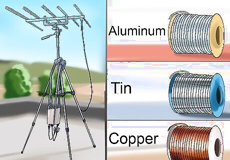
Use materials that match easily. Antennas can be made from many different materials. Remember that you should use metal of similar nature, as dissimilar metals have a tendency to corrode, or to have a non-conductive properties. Metals such as copper, aluminum, tin, and steel all will conduct electricity, but when we are talking about Radio Frequency, or RF currents and voltages, we are talking about "Skin Effect" electricity. Aluminum antenna wire is hard to work with, has a very easy breaking point, and oft times, stretches out of shape, and cannot be soldered using conventional solder. Aluminum wire is not expensive, but it is the least desirable wire for antenna use. Copper house wire prices have skyrocketed in the recent months. Finding old house wire is the best choice. Diameter of 12 gauge wire is about 1/8th inch thick. Its not hard to work with, and is probably the best antenna metal. Tin wire, used for electric fence purposes make an excellent wire antenna, and it is not to expensive. The only draw back is that you have to purchase it in either ⁄4 or ⁄2 mile (0.4 or 0.8 km) rolls. If you plan on building several antennas, you should have no problem with this large roll of wire.
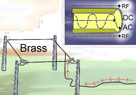
What Works with What Current. Regular DC or AC current and voltages travel through the center of the wire, whereas RF runs on the outer portions of the wire. Picture if you will, a wire with the cut portion of the wire pointing at you. If we could see the wire with the current on it, it would be easy to define. AC and DC currents would be from the center out. RF though, would be along the outer portions of the wire, like the skin of the wire. The type of metal used would have a conductivity scale. Of course, none of us will be using any precious metals in making an antenna, but the rare metals, gold, silver, and platinum are the three most conductive metals of all, but since they cost so much, we have to settle for copper wire, steel with either a brass, or copper coating, or perhaps tin, with or without copper coating, or plain electric fence type tin wire, or possibly aluminum wire if you have no other wire to use. Any good conductor of electricity will conduct RF. The least favored is the mechanic wire, which has a high resistance, and corrodes and rusts easily, causing unwanted resistance, and antenna failure. When subjected to the weather, mechanic wire will rust easily, creating a never ending problem of either breakage, or a problem of MAJOR non-connectivity. It does NOT radiate RF energy well, and doesn't receive signals from other amateur stations transmitting to you. One of the best, and probably the cheapest is the electric fence wire that is coated with brass, or copper. Since we are dealing with "skin effect" properties, just the outer coating will bear the RF energy. Steel wire also should be avoided if possible. Steel will rust easily, even if it is coated in brass or copper. Tin wire that is used for electric fence wire that is not coated, also can be used, but make sure that you inspect the connections from time to time to remove any corrosion, and re-solder them if necessary. Insulated house wire that is solid copper can make one fantastic wire antenna. At least seventy (70) percent of all amateur radio antennas are made of some sort of insulated, or non - insulated wire. Those are the ones we will be talking about here in this article.
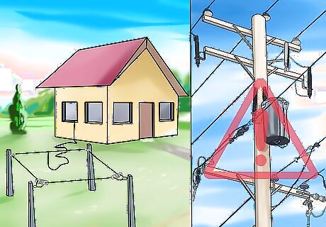
Start by choosing your place, and space for your antenna. You should NEVER be close to a power line that is energized. Many people have been seriously injured or have been fatally electrocuted due to their contact with high power transmission lines. It takes just one touch from these high power lines to kill someone who is trying to put up an antenna. Look for low hanging power lines, and stay away from them at least by one and a half lengths of the height of your longest pole closest to the power wires. The closer you are to your radio room, the better off you will be. Back yard antennas, right close to your radio room, or radio shack, make it easy to set up and operate. Try to avoid placing any portion of your antenna close to the place where electricity enters your home. Use good straight wire, and avoid serious bends or twists in the wire. If you are using tin with copper or brass coatings, watch out for the tendency to coil back onto the wire. Some tightly wound wire may also coil back on itself, regardless of what it is made from, or coatings. Some wires also have a tendency of having sharp ends when cut. Steel is the worst. Good sharp side cutter pliers, or diagonal cutters can also leave a ridge that is sharp if using certain metals. The smaller the wire, the harder it is to work with also. Using wire of light gauge, either 17, 18, right through 22 or 24 gauge, has many problems, not the least of which is its durability. Wind can destroy an antenna in a few moves with small gauge wires 17 through 22. I recommend using not less than 18 gauge for most antennas. There are places, that we mentioned earlier, that won't allow antennas, towers or antenna poles to be constructed. A dipole in the attic of your home is a good idea if you have enough space in your attic to place one. Folded dipole antennas will work great if you do not have a metal roof.
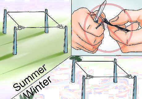
Select the wire you want to use. Make sure it is a wire that can withstand the weather, both summer and winter, and that it is of a workable nature. In other words, don't use a wire that can cause problems down the road when it is actually put into use. Insulated copper house wire is excellent. Please! do NOT remove the insulation! As a matter of a fact, the life of the antenna can greatly be extended if you do leave the insulation on the wire. Also, it insulates it from a short against a green tree, or tree leaf, or even a weed, or branch that may fall. Make sure that if it is bare wire, that you keep it up from the ground, (and we will get into that also later ) so no unsuspecting person comes in contact with the line, in the event it is energized with RF currents. RF burns can hurt, and burn deeply into the flesh of a finger or hand. RF is a sort of invisible energy, and it is the forced movements of electrons along a given path that is an AC style current.

Many tuned circuits of today's time can actually go down to several layers of skin with just one touch. It burns, and sometimes actually fries your skin into a white powder. This is called "RF BITE" since it feels like you got bit by some sort of bad bug, or stung by a bee that has no poison, but can seriously hurt. Amplified RF also hurts worse, due to the added power applied to the antenna. If you are using a tube type amplifier, depending on the wattage it has been tuned to, can and will give you one powerful bite,!, and it will hurt badly.
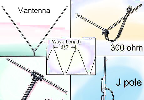
Make your antenna by the tried and true formulas. Dipole antennas often are the easiest to build, and then turned into inverted V antennas by raising the center of the antennas up into the inverted V style. It's a good idea to have your antenna at least one half ( 1/2 ) wavelength of the antenna. one quarter (1/4) wave is the minimum height above ground for effective performance. Wire "J" poles for VHF are easily built, and can be used in an emergency. These inventions simply use the ever popular 300 Ohm antenna lead in wire. You can use them for any frequency, including the HF bands, but you will need a tall tower, or a high tree to hang them high in the sky. As of this writing, 300 Ohm antenna wire is pretty scarce. A roll of 300 or 450 Ohm antenna wire was $55.00 just a year ago. Now if you can find it from any source, the same roll costs $95.00.
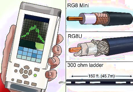
Here's several other feed lines you may consider to use. Choose which ever line fits your particular need. RG8 mini 8 can handle up to 2 kilowatts. RG8U, which is the large wire, with either foam or plastic center insulator and can be used up to 3 kilowatts, Hard line such 9913 series is the best for VHF or UHF transmissions. 300 Ohm covered ladder line is great if you have a long run, say more than 150 feet (45.7 m). Open feed line is trouble, but you can use it, IF IT DOESN'T act like like an antenna. If you cut open ladder line in less than a wave, it can act as your antenna instead of your radiator antenna element. Avoid using odd lengths of transmission line, and try to do the wave lengths version to prevent parasitic transmissions, and falling on your neighbors antenna, or bleeding off into someones cell phone, or perhaps even setting off home alarm systems that are close in your neighborhood. Car alarms that are not shielded can oft times be set off by using certain frequencies. Please take note here, if you are running amateur radio, and it's been checked out, it's NOT your fault that your neighbors are having problems. It's the poor design, shielding and the sensitivity of their equipment that is at fault. Sometimes, a solution can be reached, other times, there is no solution other than they have to put a filter, or a suppressor on their equipment to keep their equipment from malfunctioning, and acting as a receiver. The FCC also states that our equipment must not cause unwanted interference from occurring. In order to defend yourself, make note of the frequency you were using at the time the incident occurred, and if you have not had your equipment tested, have your equipment put on a spectrum analyzer, or a harmonic detector to PROVE your equipment is NOT causing any unwanted interference. If your equipment is clean, then it's up to the other party to take action to prevent them from getting on the ham band.
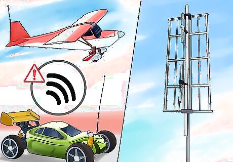
Screen your VHF and MHF bands. There are frequencies that we use that can cause malfunctions of RC cars, airplanes and robots. Its not the hams fault. It's mainly due to a flaw in design, shielding or it could be that these toys are acting as a receiver. Such was a case not long ago, and we will discuss the outcome of that incident, but first let us talk building antennas.
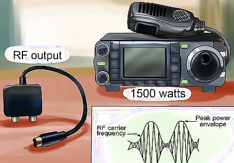
Maximum output! What is maximum output.? The term Peak Envelope Power or PEP, is the maximum output power allowed by law peak to peak envelope, cycling from an AC source, RF output. With recent changes to some laws, the local government can also regulate how much power you can use. Legally, Amateur radio operators can run up to 1500 watts! That's a lot, but consider this, a ten thousand dollar set up with a 50 cent antenna, isn't gonna serve you well. Whether you live in the country, or in the city, the antenna is the root of good transmit / receive functions.
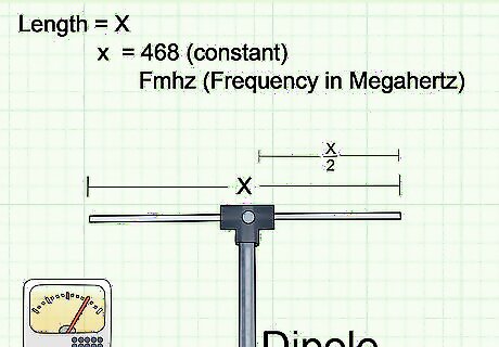
Formulate then make! The way to find out what length you need for a DIPOLE antenna, which is the most common antenna used, you use mathematical equation, 468/ FMhz whereas, 468 is the one standard, the fMHz is Frequency in MEGAHERTZ, and that give you the total length of a dipole antenna in feet. Divide by 2 and place a ceramic, dog bone, or even PCV pipe insulator between them in the middle where you just cut, and you got a dipole antenna. Attach a feed line, and run to your tuner, or if you are gonna use resonant antennas, attach to your SWR meter, and check for high SWR readings. Usually, less than a 1:5 to one or less is acceptable, but a 1:1 match reading is the very best. Using resonant antennas can be the most fulfilling experience of antenna use, however space and materials can pose a factor in using several antennas that are resonant to each band.
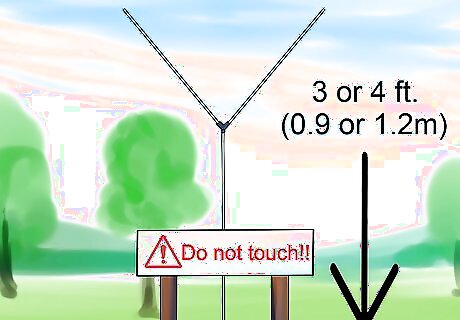
Raising or lowering the antenna can help with SWR, but also one more thing to keep in mind, It's a good idea to raise the antenna at least 1/4th wavelength above ground. Inverted V antennas can be tied off as high as possible, but can go as low as 3 or 4 feet (0.9 or 1.2 m) from the ground. Place a warning sign on the tie off point if your antenna is low enough to touch, telling anyone that high voltages can be present at any time, and not to touch the wire in any way.
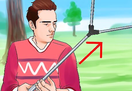
Stretch out the legs of the antenna as much as possible, and pull them as high in the air as possible. The more capture area that is available, the better the transmit or receive. Secure line with good strong, nylon or rayon rope. Use either ⁄4 or ⁄2 inch (0.6 or 1.3 cm) plastic nylon or rayon rope, and then you will find that these works best, but you should inspect them at least twice a year for frays, or weathering problems. Replace if necessary.
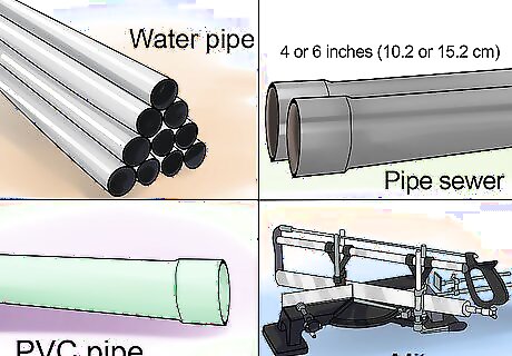
Making a new design ! For many years now, designing antennas has been a passion for many a ham operator. The next one on the list is a cage dipole. For this, you will need either 4 or 6 inch (10.2 or 15.2 cm), thick wall PVC sewer, or water pipe, and a way to cut it in either ⁄4 or ⁄2 inch (0.6 or 1.3 cm) spreaders. Use of a compound mitre saw makes this job easy. Use a 12" saw to cut the 6 and 4 inch pipes. WATCH OUT THOUGH, SINCE THE LAST FOOT OF THE PIPE COULD BUCK AGAINST THE SAW and may not cut through the pipe, and throw it back at you. Cut only where it will NOT be dangerous. usually 12 to 14 inches (30.5 to 35.6 cm) of the pipe will be left. If you own, or have a friend who owns one of the saws, use it to cut the pipes. Once they have been cut, measure the outside diameter of the pipe spreaders on the OUTSIDE in metric CM and MM. After you have the circumference, divide by 6 if you are using 6 wires, or divide by 8 if you plan on using 8 wires for this project. After you have the pattern down, use a drill with a 1/8th or a 5/32ths drill bit, depending on the gauge wire used to put 6 or 8 holes in each spreader. Be accurate as possible.
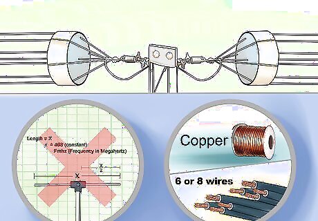
Do not use the SAME FORMULA FOR THE CAGE DIPOLE. It will be shorter than a regular dipole! It is relative to the size spreader used! You can only use the original formula as a starting point. Depending on spreader size you may have to reduce the length by as much as 4% or more!Just remember that you will either use 6 wires or 8 wires. Electric fence wire is often a choice in this type of an antenna, as it is relatively inexpensive, and can be bought in large rolls of one quarter or half mile or more wire on one spool. Tin wire will work in this project, however copper is best Using anything other than copper can compromise performance
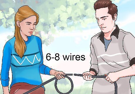
Measure carefully, although not critical at this point. It's always better to go a little too long, than too short, and then have to add wire. Cut full run lengths of 6 or 8 wires. Its always a good idea to have a couple friends working with you when it comes to this project. Make the wires you have cut come together at the center when you have done your measurements.
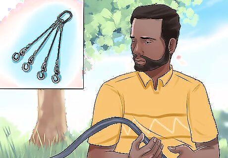
Assembling your antenna, and this where the fun comes into play. Slide 5 spreaders on the wire, using 4 of them, easing them all the way down to the other end. Next, space the spreaders with the wires through the holes at intervals of either 18 or 20 inches (45.7 or 50.8 cm) apart. Put contact cement on the tooth picks, or match stems before sliding them into the holes with the wires to hold them firm. Leave one spreader at the first end, that way, it will show you where to place your wires into the spreaders. Continue with the spreaders, using 4 or 5 spreaders at a time, leaving one at the end each time. Tighten wire, and then peg the wires with the sharp toothpicks, or wood matches, using ONLY the wood on the matches. After you reach the end of one side of the cage, gather up all the loose wires at both ends, and tie them together using a piece of wire, wrapping all wire ends together near the center of the spreader. Lay this leg of the dipole aside, and do the same with the other leg.
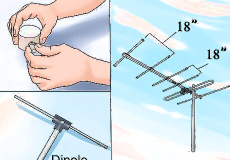
Make it "Count". Whether you use 18 inch (45.7 cm) or 20 inch (50.8 cm) spacings in between the spreaders, to make it look good, don't change the spreaders in alternately positions. If you use 18 inch (45.7 cm) spacings, use them all the way to the end of the antenna. If you use 20 inch (50.8 cm) spacings, use all spacings at 20 inches (50.8 cm) apart. Larger wires in gauges of 14 or 12 can add weight to this project, so it takes a lot to get these antennas going. Don't rush this project! Take your time, do it right the first time, and then, you can rest assured that your antenna will serve your purpose. The capture area of a 6 wire cage dipole has increased 5 times ! An EIGHT wire antenna increases gain of capture by 7 ! Although it is hard to work with, and build this antenna, for amateur radio use, it's one of the best.
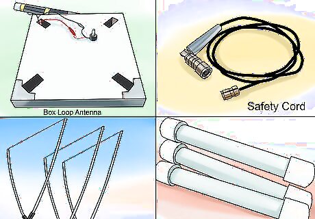
ZOOM-XOOM-and Voila ! One of the best kept secrets of Amateur radio antennas are either the box, or delta loop antennas. Resonant antennas cut to the exact frequency, in the middle portion of the band, and used with a tuner of sufficient size, can tune several bands. The formula used to find a full wave loop antenna is 1005 / FMhz. This gives you the length of a full wave loop antenna for the band you are using. Horizontal positioning into a TRIANGLE shape, makes it a DELTA loop, If you put it into a square, or rectangle shape, you have a BOX loop antenna. Out in the country is where this antenna is most often used. It requires a large area of land, and also it can be fed either in the middle, or an end portion of the loop. When hoisting this little monster of an antenna into the air, watch out, as we said before, for POWER LINES~! Trees that are spaced far enough apart provide ample heights above ground for this antenna. Trees are often called, "Poor Mans Towers" and either can be accessed for use by using several methods, including a good fishing pole and a 4 ounce sinker, properly aimed at a high branch in the tree. When it is successful, tie a masons line, or even affix the rope you are going to use to the line, and gently roll in your catch over the branches of the tree, and pull it down to the ground. Don't forget to use adequate lengths of rope, or safety cord for this project. You can use PVC pipe here as an insulator. Cut 3 or 4 pieces of 1 ⁄2 inch (3.8 cm) PVC pipe about 6 or 7 inches (15.2 or 17.8 cm) long. Drill ⁄2 inch (1.3 cm) holes using a good drill bit, and never drill close to the end of the pipe. About 2 inches (5.1 cm) from the end gives you a good spacing for the insulators. For the feed point, use yet another piece of PVC pipe, drilling a hole through the center to provide for a strain relief for the feedline. Put the stress on the pipe, not on the antenna or on the feedline. Pull up your antenna into the trees or your tower very carefully, making sure that it is as close as possible to the design you chose to make the antenna. Box or rectangle loop, or a triangle, spacing them out as much as possible. Yes, you can fudge a little if you have to on the sides, making one a little longer, but its best to keep your antenna as practical as possible to the design.







Comments
0 comment