views
Reading the Digital Display
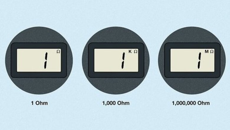
Determine the scale of the readout by looking for a “K” or “M” beside the omega. The omega symbol on your digital ohmmeter screen indicates the ohm level. However, if the resistance of whatever you're testing is in the kilo-ohm (1,000 ohms) or mega-ohm (1,000,000 ohms) range, the display will add a “K” or “M,” respectively, in front of the omega symbol. For instance, a reading that says 4.3 with only the omega symbol indicates 4.3 ohms. A reading that says 4.3 with a “K” before the omega symbol means 4.3 kilo-ohms (4,300 ohms).
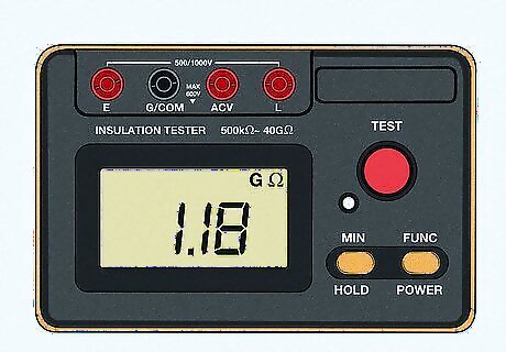
Read the resistance value. Apart from understanding the scale of the digital ohmmeter, understanding the resistance value is the main element of the ohmmeter reading process. The numbers are typically front and center in the digital display, and usually extend to one or two decimal points. Resistance is a measure of how much a device or material reduces the electric current flowing through it. Higher numbers indicate a higher resistance rating, which means more energy will be required to integrate the component in a circuit. When you test a resistor, capacitor, or another electronic component, the ohmmeter will display a number indicating its resistance.

Look for “1,” “OL,” (“over loop”) or a couple of dashed lines for an indication that the range is set too low. If you aren't using a meter with an auto-range function, you'll need to set the range yourself. To avoid setting the range too low, always start at the highest possible range and work your way down to lower ranges until the ohmmeter registers a reading. Do this even when you know the range of the component you're testing.
Using the Meter
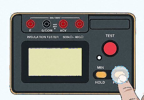
Turn the meter on. The process by which your turn your ohmmeter on will vary depending on the model you're using. Typically, you can just thumb the switch that says “Power” or “On/Off.” Consult manufacturer directions for more information about how to select the resistance function on your multimeter.
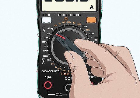
Select the resistance function if you're using a multimeter. An ohmmeter is included in the suite of tools available in the multimeter, a device that also functions as an ammeter and voltmeter. The exact method by which you select the resistance function will vary somewhat depending on the model of multimeter you're using. Look for a rotating switch or dial to change the setting. Consult manufacturer directions for more information about how to select the resistance function on your multimeter.
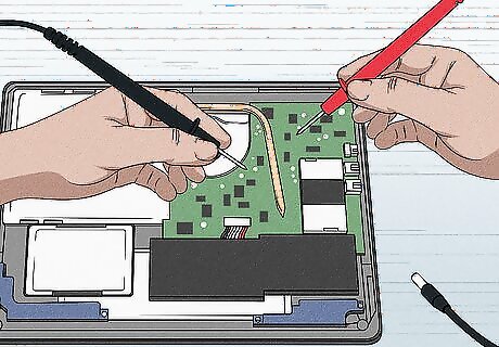
Test resistance in a circuit when it is unpowered. In other words, don't connect the circuit to a power supply when using your ohmmeter. Doing so could damage your digital ohmmeter or invalidate your resistance reading.
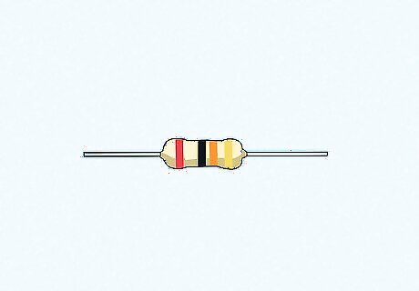
Take individual components out of the circuit before testing them. If you want to measure the resistance of an individual component (for instance, because you suspect it is faulty), remove it from the circuit, then test the component by touching the leads to the two poles of the component. This will give you a baseline reading against which you can later test the circuit. The precise method by which you remove individual components depends on what the component is. For instance, if you're testing a capacitor, you'll need to remove it with a soldering iron and discharge any remaining electrical energy from it.
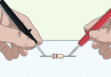
Test the resistance of an electrical component using the test leads. When you're ready to test components for resistance readings, touch the test leads to the leads of the component. These leads typically appear as two thin silver wires poking out of the component. Even within the same type of component, the placement of these leads varies. For instance, in some capacitors, the leads both exit the same side. In other capacitors, one lead will poke out of one end while the second lead pokes out the opposite end. If you're having trouble identifying the leads of the component you're interested in testing, consult manufacturer directions. It doesn't matter which test lead and which component lead you touch together.
Setting the Range
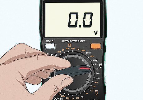
Use the auto-range setting if possible. Most digital ohmmeters have an auto-range function that eliminates the need for you to figure out the right range. This saves time and energy, and enables you to start using your ohmmeter sooner. The auto range setting might be inbuilt, or you might need to select it from a menu. Consult your user guide for more information.
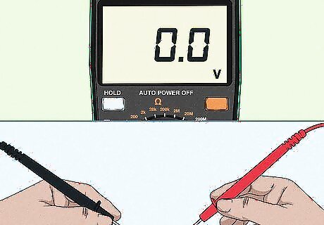
Start at the highest range on your ohmmeter. Always set the range to the highest setting available when you first start testing to see if you can get an accurate reading. Hold the probes of the ohmmeter against the sides of the circuit to take your reading. If the range is too high, then the reading will stay on 0 or close to it. If you set an analog ohmmeter's range too low, it will cause the needle to snap rapidly to one side, potentially damaging it.
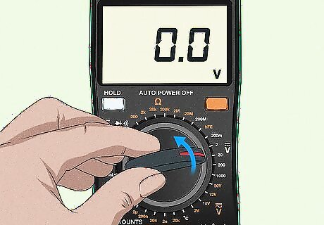
Turn the range down on the ohmmeter 1 step at a time to test the circuit. If the range is too high for a circuit, the reading may not be accurate or it will be hard to see. Use the range adjustment buttons on a digital meter or turn the dial lower on an analog meter to lower the range by 1 step. Test the probes on the circuits again to see if your reading is more clear. If not, keep adjusting the meter lower until you're able to see the reading. If you make adjustments to the ohmmeter's range, you may need to calculate the ohms using multiplication or division. Follow the instructions for your ohmmeter carefully to learn how to adjust your measurements.


Comments
0 comment